Draft Documentation
This page is currently under development. Content may be incomplete or subject to change.
System Modeling#
System modeling in SysGit defines the physical and logical structure of your system—the parts, their attributes, their interfaces, and how they connect together. While requirements describe what the system must do, the system model describes what the system is and how it's organized.
This structural foundation enables requirement allocation, interface management, and ensures that every requirement has a home in the architecture.
Understanding System Models#
What is a System Model?#
A system model is a structured representation of your system's architecture. It captures:
- Physical decomposition: How the system breaks down into subsystems, assemblies, components, and parts
- Logical organization: How functions and capabilities are grouped, even if they span physical boundaries
- Attributes: Characteristics and parameters of each element (mass, power, dimensions, etc.)
- Interfaces: How parts connect and communicate with each other
- Allocation targets: Where requirements are assigned for implementation
In aerospace and defense, the system model is the bridge between requirements and detailed design. It ensures that nothing is overlooked and that all requirements have a clear path to implementation.
Why Model Your System?#
Requirement allocation: Requirements must be assigned to specific subsystems and parts. Without a system model, you have nowhere to allocate them.
Interface management: Complex systems have numerous interfaces between subsystems. The model captures these relationships explicitly.
Mass/power budgets: Attributes in the model enable roll-up calculations—total system mass, power consumption, cost, etc.
Subsystem responsibility: In multi-vendor programs, the model defines boundaries between organizations. Clear subsystem definitions enable parallel development.
Change impact analysis: When a part changes, the model shows which interfaces are affected and which requirements need review.
Communication: The model provides a common language for electrical, mechanical, software, and systems engineers.
Getting Started with Parts#
Navigate to System View#
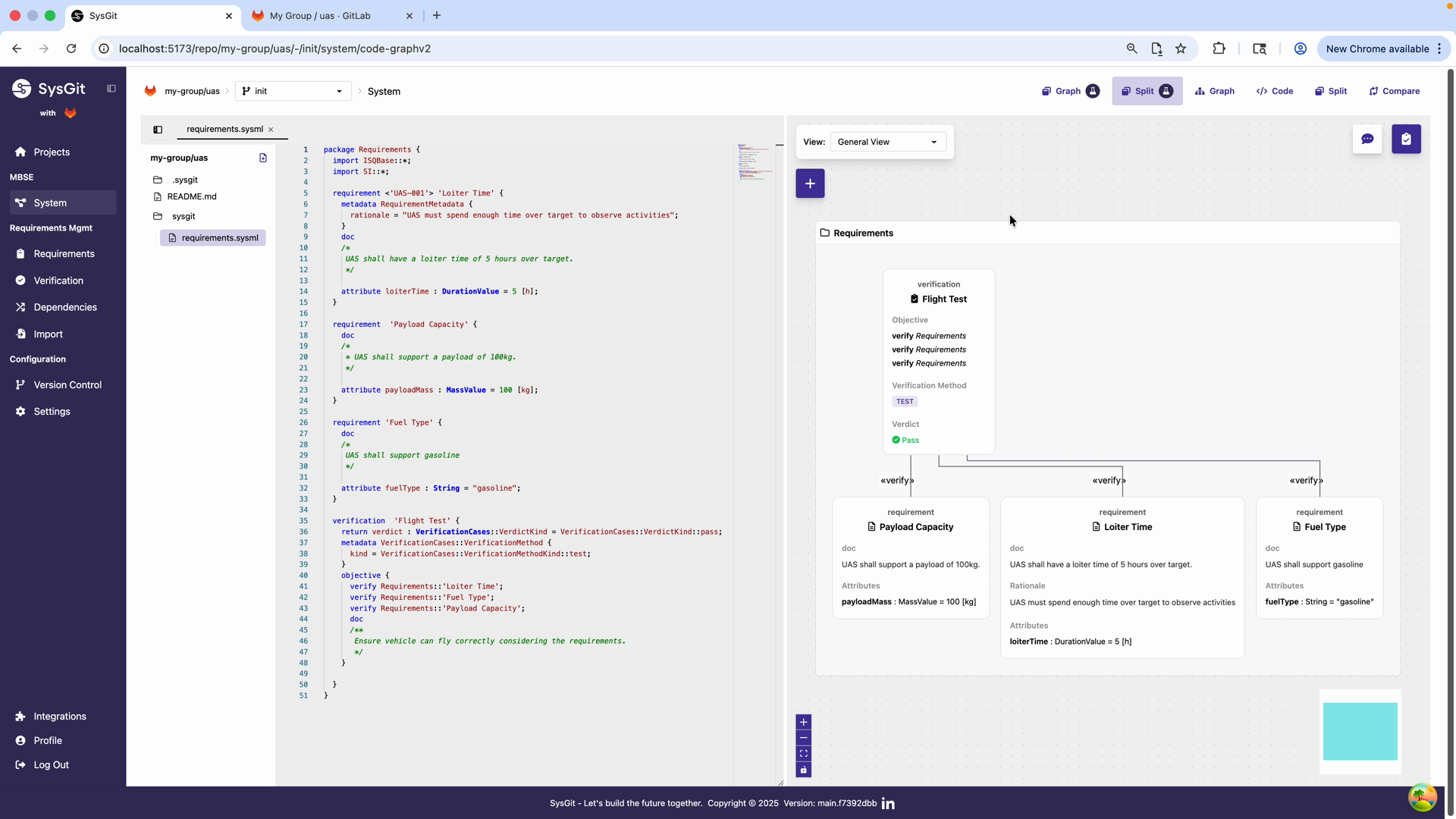
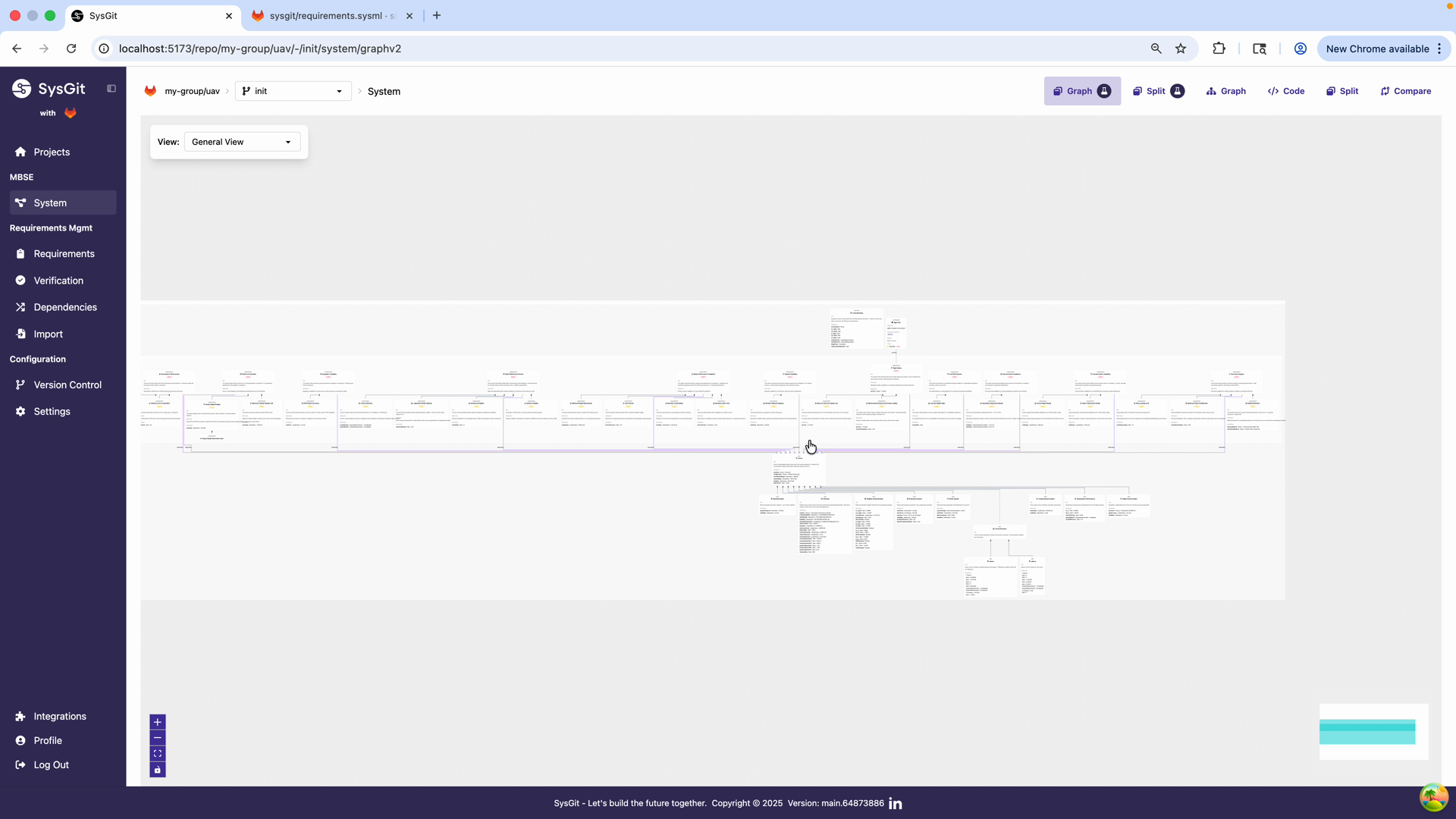
Start from the System view, which provides both the textual SysML v2 code editor on the left and the visual dependency graph on the right. At this stage, you'll see your existing requirements and verifications but no parts defined yet.
The interface shows:
- Code editor (left): SysML v2 textual notation
- Visual panel (right): Graphical representation of system elements
- Navigation sidebar: Access to different views (Requirements, Verification, Dependencies, etc.)
Add Parts Using the Visual Interface#

To add a part:
- Right-click in the visual panel or click the "+" button
- Select "Add object to Requirements"
- From the Type dropdown, select Part Usage
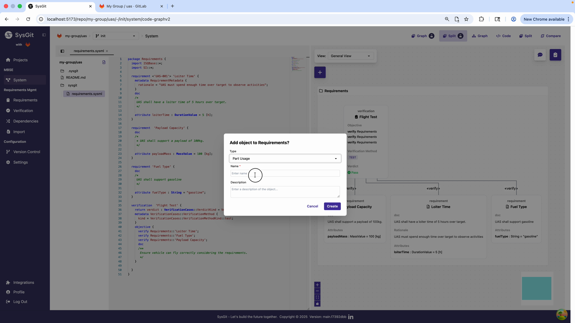
Part Usage is the correct type for defining system components in SysML v2. This creates a structural element that can contain nested parts, attributes, and ports.
Define Your First Part#

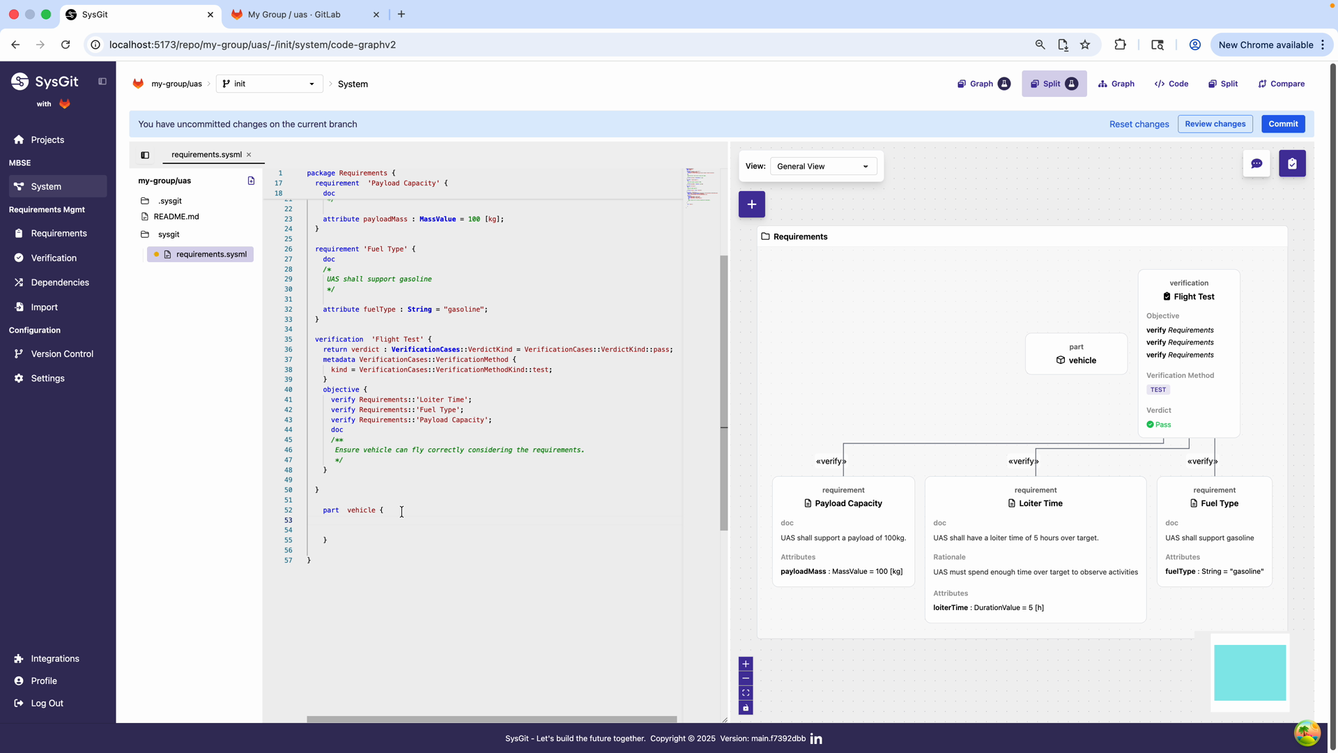
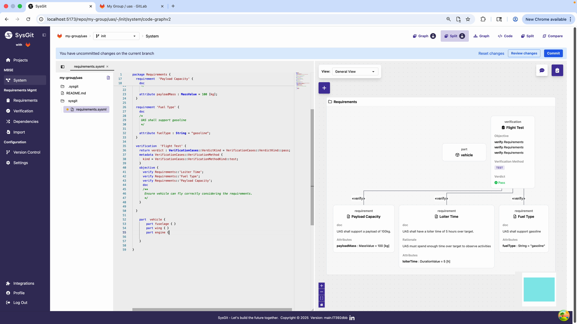
Name your top-level part (in this example, "vehicle") and create it. The system automatically:
- Generates the corresponding SysML v2 code in the editor
- Adds a visual representation in the dependency graph
- Shows the part definition in the code:
part vehicle { }
Note the banner indicating "You have uncommitted changes on the current branch" - SysGit tracks all modifications using Git version control.
Part Definitions vs Part Instances#
SysGit distinguishes between part definitions (templates describing a type of part) and part instances (specific occurrences of that type in your system).
Part Definitions#
A part definition (written part def in SysML v2) describes a reusable type of component:
part def Battery {
    attribute capacity : Real [mAh];
    attribute voltage : ElectricPotentialValue [V];
    attribute mass : MassValue [kg];
}
This defines what it means to be a Battery—every battery has capacity, voltage, and mass. But this doesn't represent a specific battery in your system.
Use part definitions for:
- Standard components that appear multiple times
- Vendor-provided parts with defined specifications
- Reusable subsystem templates
- Interface definitions shared across the program
Part Instances#
A part instance (written part in SysML v2) is a specific occurrence of a part definition or an inline part:
part drone : UAV {
    part 'Power System' {
        part mainBattery : Battery {
            attribute capacity = 5000.0 [mAh];
            attribute voltage = 14.8 [V];
            attribute mass = 1.2 [kg];
        }

        part backupBattery : Battery {
            attribute capacity = 2500.0 [mAh];
            attribute voltage = 14.8 [V];
            attribute mass = 0.6 [kg];
        }
    }
}
Here, mainBattery and backupBattery are both instances of the Battery definition, but with different parameter values.
Use part instances for:
- Specific occurrences in your system architecture
- Parts with unique parameter values
- Building the actual system decomposition hierarchy
When to Use Which#
Use part definitions when:
- You have multiple identical or similar parts in the system
- You need to reference the same component type in different contexts
- You're defining standard interfaces or templates
- You want to establish a library of reusable components
Use inline part instances when:
- The part is unique to this location in the hierarchy
- You're quickly building system structure
- Parameters are specific to this occurrence
- You don't need reusability
Most complex systems use both: standard part definitions for common components (batteries, connectors, processors) and inline instances for unique assemblies.
Building System Hierarchy#
System architecture is inherently hierarchical. An aircraft decomposes into propulsion, avionics, structures, etc. Each of those decomposes further. SysGit represents this hierarchy naturally through nested parts.
You can build the system architecture either through the visual interface or by directly editing the SysML v2 code. For efficiency, add multiple nested parts using the textual notation:
part vehicle {
    part fuselage { }
    part wing { }
    part engine { }
}
This defines a vehicle composed of three major subassemblies: fuselage, wing, and engine.
Automatic Visual Updates#
As you type the SysML v2 code, the visual dependency graph updates in real-time. Each nested part appears as a child node of the vehicle part, showing the hierarchical structure of your system.
The visual representation helps you:
- Verify the structure is correct
- Understand relationships at a glance
- Identify missing components
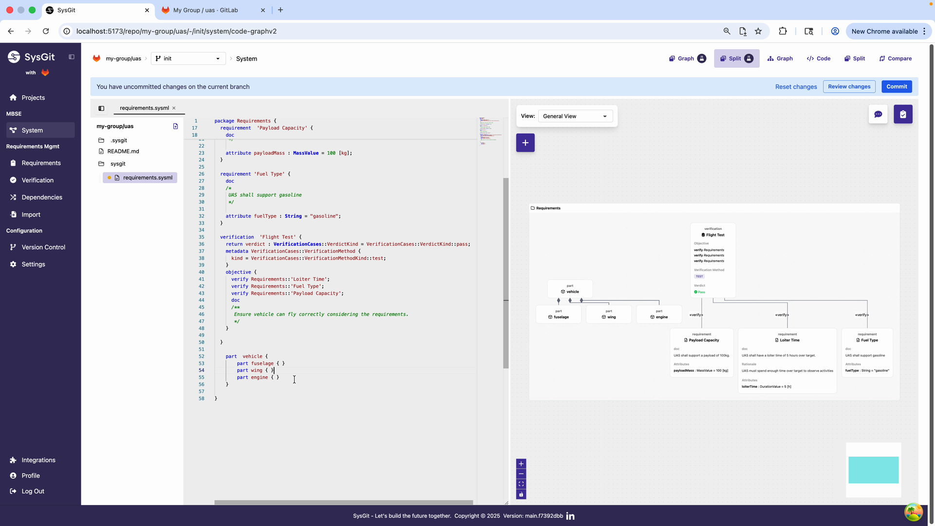
The hierarchy now clearly shows:
- vehicle (top-level part)
- fuselage
- wing
- engine
Creating Top-Level System#
Start with your top-level system part. This represents the entire deliverable system:
package System {
    part 'Complex Drone System' {
        // Subsystems will go here
    }
}
This top-level part serves as the root of your decomposition tree. All subsystems, components, and details nest within it.
Adding Subsystems#
Decompose your system into major subsystems. For a drone, this might include:
part 'Complex Drone System' {
    part 'Propulsion System' {
        // Propulsion components
    }

    part 'Power System' {
        // Batteries, power distribution
    }

    part 'Flight Control System' {
        // Flight computer, sensors
    }

    part 'Communication System' {
        // Radios, antennas
    }

    part 'Payload System' {
        // Mission-specific equipment
    }

    part 'Airframe' {
        // Structure, aerodynamics
    }
}
Each subsystem becomes a container for further decomposition. This matches how engineering teams organize—propulsion engineers work on the Propulsion System, avionics engineers on Flight Control System, etc.
Further Decomposition#
Continue decomposing until you reach a level appropriate for requirement allocation:
part 'Airframe' {
    part 'Aerodynamic Performance' {
        // Wings, fuselage for aerodynamics
    }

    part 'Stability Characteristics' {
        // Tail, control surfaces for stability
    }

    part 'Control Surfaces' {
        part elevon1 : ControlSurface {
            attribute deflectionRange = 30.0 [deg];
        }

        part elevon2 : ControlSurface {
            attribute deflectionRange = 30.0 [deg];
        }

        part aileron : ControlSurface {
            attribute deflectionRange = 25.0 [deg];
        }
    }
}
The depth of decomposition depends on your program's needs. Large programs may go 5-6 levels deep. Smaller programs may stop at 2-3 levels.
Best practice: Stop decomposing when you reach parts that:
- Represent a clear work package for a single engineering team
- Have well-defined interfaces with other parts
- Can have requirements meaningfully allocated to them
- Match your organizational structure or vendor boundaries
Part Attributes#
Attributes capture the measurable characteristics of parts. These enable analysis, budgets, and trade studies.
Adding Attributes Visually#
To add an attribute:
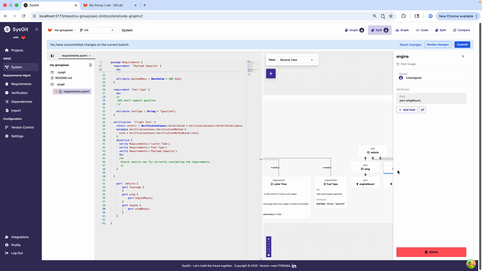
- Select the part in the visual panel (e.g., wing)
- In the part details panel, click "+ Add field"
- A dialog appears for defining the attribute

Define the attribute properties:
- Attribute name: wingspan
- Select type: LengthValue (from ISQ library)
- Value (optional): 20 [ft]
This creates typed, unit-aware attributes that support automated analysis and verification.
Generated Attribute Code#

The visual interface generates proper SysML v2 code for the attribute:
part wing {
    port engineMount;
    attribute wingspan : LengthValue = 20 [ft];
}
This demonstrates how SysGit seamlessly translates visual operations into standards-compliant SysML v2 textual notation. The attribute is:
- Typed: Uses LengthValue from the ISQ (International System of Quantities) library
- Unit-aware: Includes unit specification [ft]
- Quantified: Has a numeric value (20)
Common Attribute Types#
Use typed attributes with proper units:
part 'Propulsion System' {
    attribute maxThrust : ForceValue = 500.0 [N];
    attribute dryMass : MassValue = 15.0 [kg];
    attribute maxPower : PowerValue = 5.0 [kW];
    attribute efficiency : Real = 0.85;  // Dimensionless
}
Common attribute types for hardware systems:
| Attribute Type | SysML v2 Type | Example Units |
|---|---|---|
| Mass | MassValue |
[kg], [lb] |
| Length | LengthValue |
[m], [ft], [in] |
| Force | ForceValue |
[N], [lbf] |
| Power | PowerValue |
[W], [kW], [hp] |
| Voltage | ElectricPotentialValue |
[V] |
| Current | ElectricCurrentValue |
[A] |
| Energy | EnergyValue |
[J], [Wh] |
| Frequency | FrequencyValue |
[Hz], [MHz] |
| Angle | AngularMeasureValue |
[deg], [rad] |
| Temperature | TemperatureValue |
[K], [degC], [degF] |
Calculated Attributes#
Some attributes derive from others through calculations:
part 'Battery Pack' {
    attribute cellCount : Integer = 4;
    attribute cellVoltage : ElectricPotentialValue = 3.7 [V];
    attribute totalVoltage : ElectricPotentialValue = cellCount * cellVoltage;
}
While SysGit doesn't execute these calculations automatically, documenting them in the model enables external analysis tools to compute values programmatically.
Attribute Inheritance#
When using part definitions, instances inherit attributes from the definition:
part def Servo {
    attribute torque : ForceValue [Nm];
    attribute speed : Real [rpm];
    attribute mass : MassValue [kg];
}

part aileron1 : Servo {
    attribute torque = 2.5 [Nm];
    attribute speed = 60.0 [rpm];
    attribute mass = 0.08 [kg];
}
The instance aileron1 has all the attributes defined in Servo, with specific values assigned.
Requirement Allocation to Parts#
The system model's primary purpose is providing targets for requirement allocation. Every requirement should eventually be assigned to one or more parts responsible for fulfilling it.
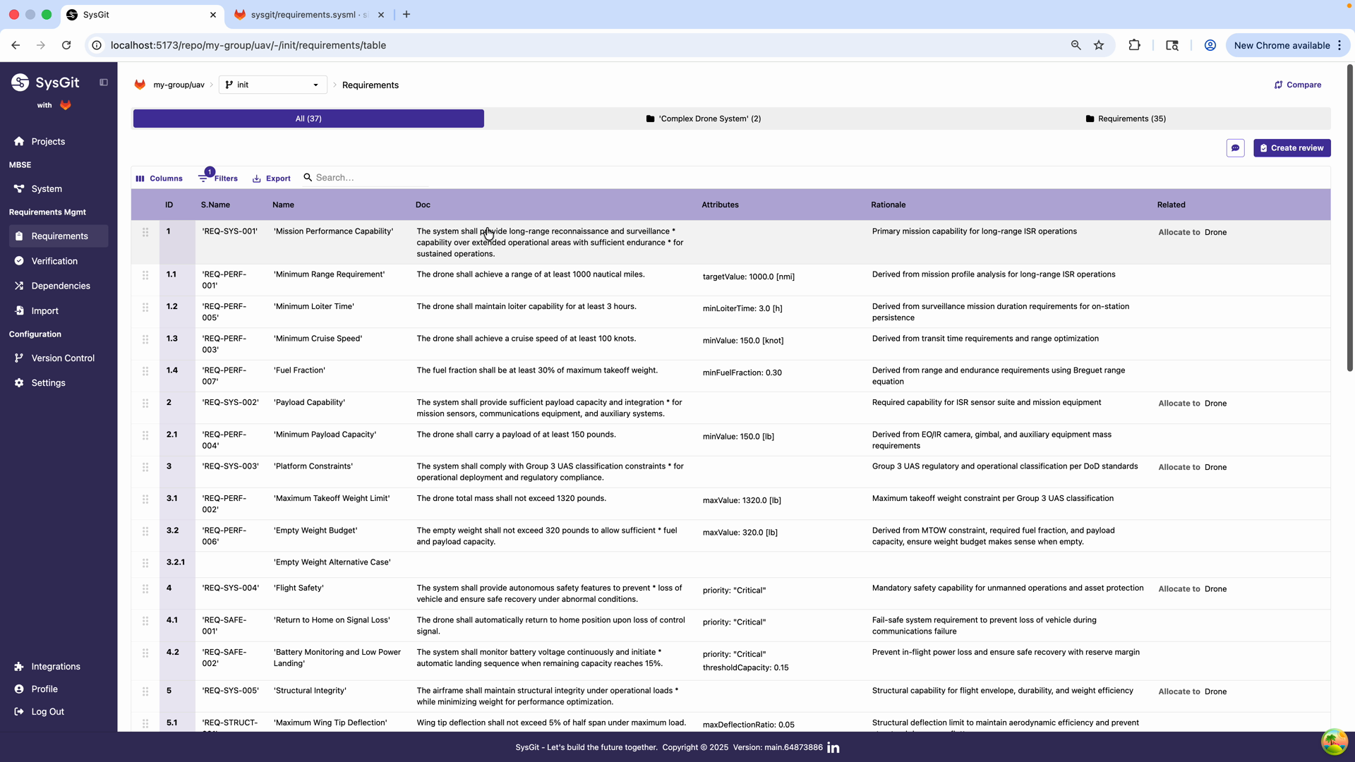
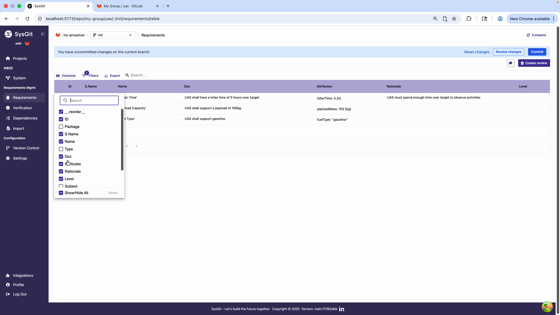
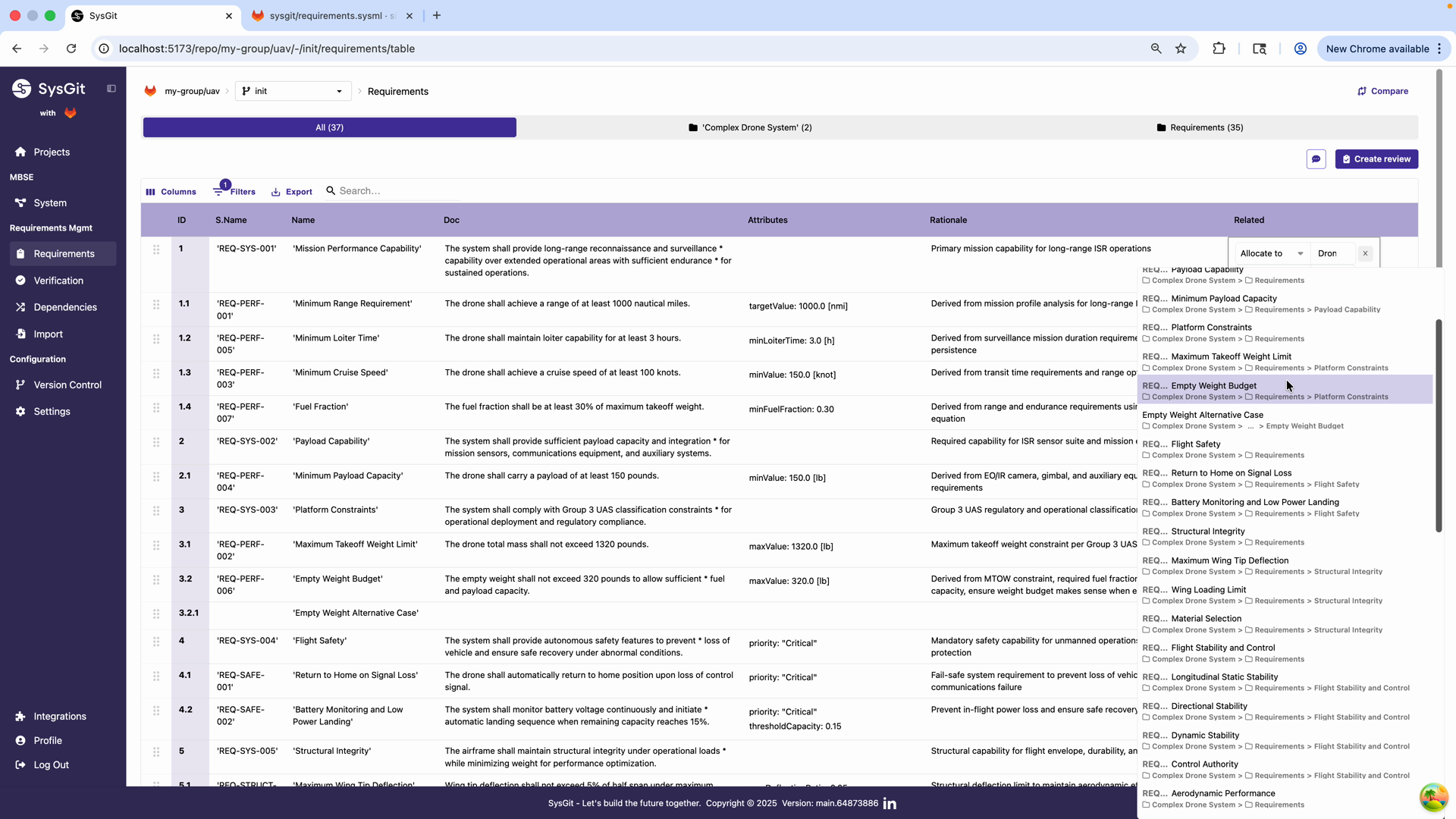
Enabling Allocation in Requirements Table#
To enable allocation:
- Navigate to the Requirements table view
- Click Columns and ensure "Related" is enabled
- This column allows you to establish allocation relationships
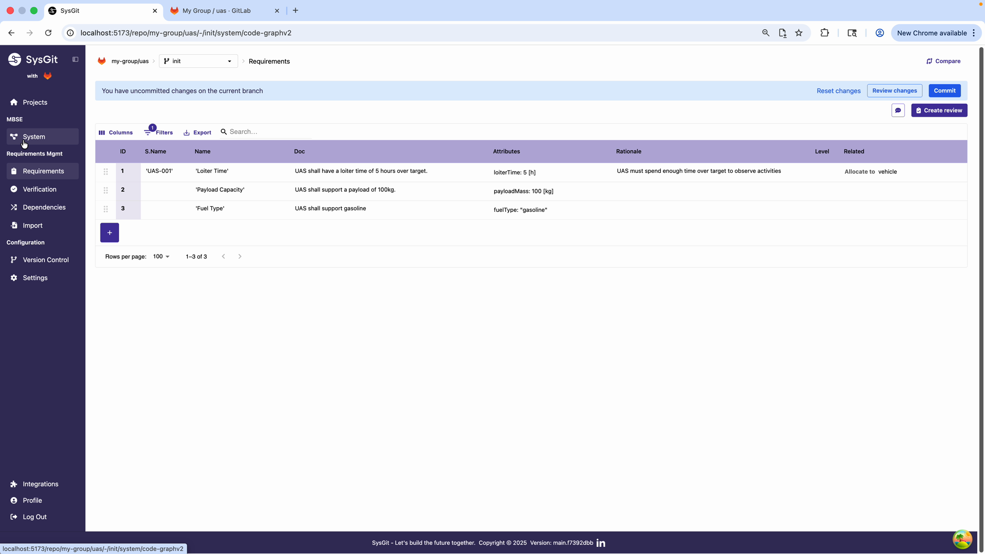
The Related column now shows allocation relationships: - Loiter Time → Allocate to: vehicle - Other requirements can be allocated to specific parts
This traceability is critical for:
- Requirements verification planning
- Impact analysis when requirements change
- System decomposition validation
Simple Allocation#
Allocate a requirement to a part using the allocate relationship:
allocate Requirements::'Maximum Speed' to 'Propulsion System';
This formal allocation means: "The Propulsion System is responsible for meeting the Maximum Speed requirement."
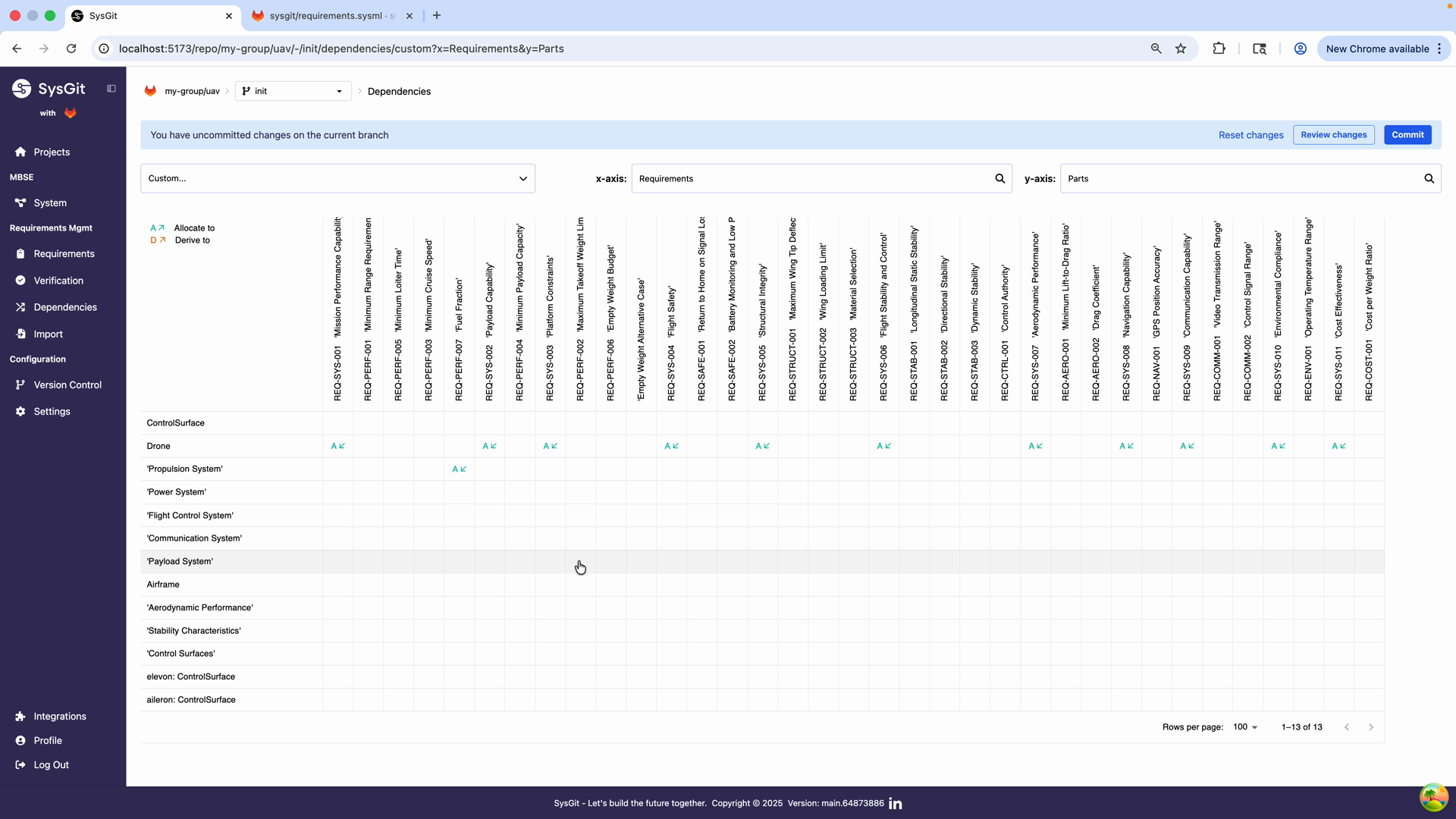
Allocation in the Dependency Matrix#
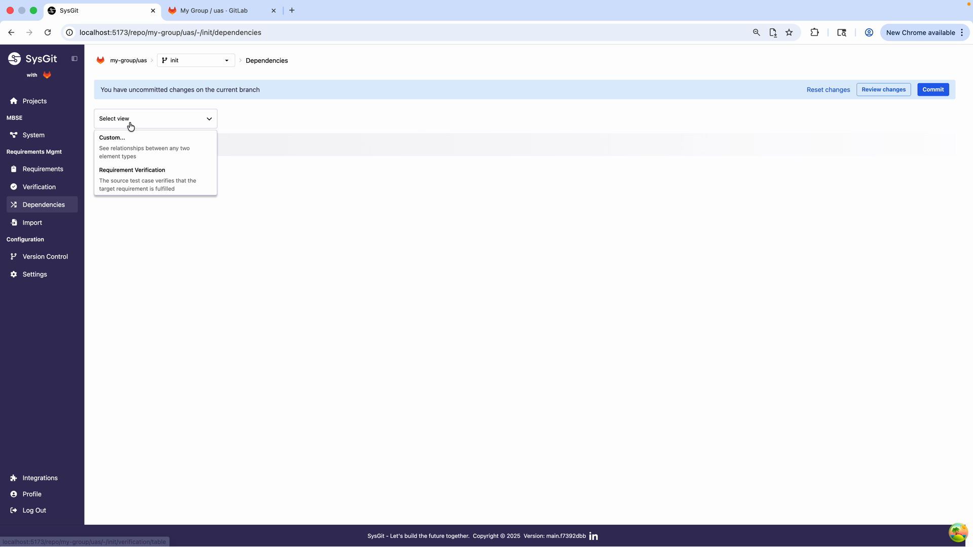
The most efficient way to establish many allocations is through the custom Dependency Matrix:
- Navigate to Dependencies from the sidebar
- Select "Custom..." from the view dropdown
-
Configure the axes:
-
x-axis: Requirements
- y-axis: Parts
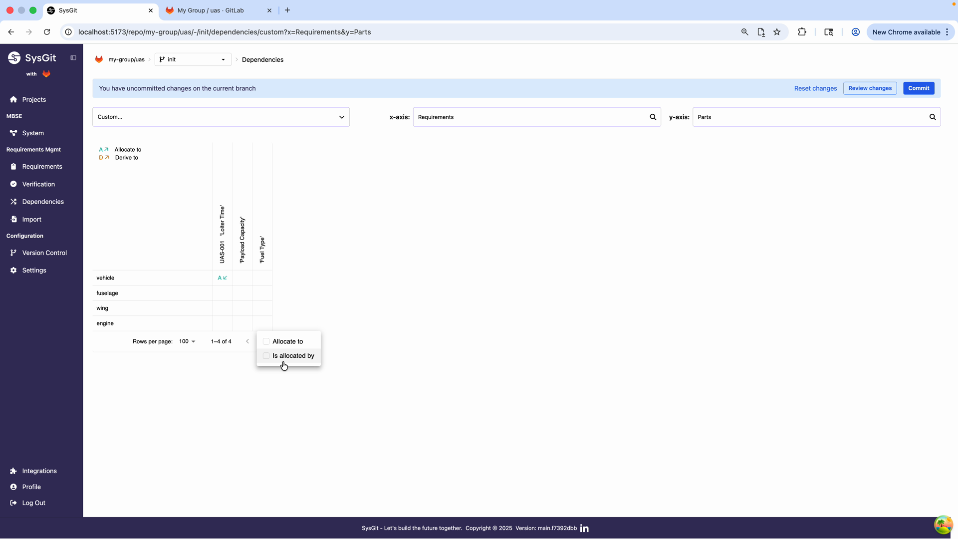
The allocation matrix displays:
- Rows: System parts (vehicle, fuselage, wing, engine)
- Columns: Requirements (Loiter Time, Payload Capacity, Fuel Type)
- Cells: Allocation relationships (shown with "A↓" indicator)
In this view, you can see that the Loiter Time requirement is allocated to the vehicle part. This relationship view supports:
- Completeness checking (are all requirements allocated?)
- Coverage analysis (which parts implement which requirements?)
- Alternative view modes: "Allocate to" and "Is allocated by"
Requirements-to-Parts Matrix#
The matrix provides instant visibility:
- Which requirements are allocated to each part
- Which parts have many allocated requirements (high workload)
- Which requirements aren't allocated (gaps)
- Which requirements are allocated to multiple parts (interfaces)
In a drone example, you can see:
'Propulsion System'has allocations for fuel-related requirements'Airframe'has allocations for structural requirements'Flight Control System'has allocations for stability requirements
Multi-Part Allocation#
Some requirements apply to multiple parts. For example, a weight budget requirement might be allocated to every subsystem:
allocate Requirements::'Maximum System Mass' to 'Propulsion System';
allocate Requirements::'Maximum System Mass' to 'Power System';
allocate Requirements::'Maximum System Mass' to 'Airframe';
// ... etc for all subsystems
This allocation pattern indicates that each subsystem must meet its portion of the mass budget. The Dependency Matrix shows these multi-part allocations clearly—one column with markers in multiple rows.
Allocation to Nested Parts#
Requirements can be allocated to parts at any level of the hierarchy:
// System-level allocation
allocate Requirements::'Mission Performance' to 'Complex Drone System';

// Subsystem allocation
allocate Requirements::'Fuel Fraction' to 'Complex Drone System'.'Propulsion System';

// Component allocation
allocate Requirements::'Battery Capacity'
    to 'Complex Drone System'.'Power System'.'Main Battery';
The hierarchical path is shown in the Requirements Table's Related column, making it clear exactly where in the architecture each requirement is allocated.
Flowdown Pattern#
A common pattern is requirement flowdown:
- High-level requirement allocated to system
- Derived requirements allocated to subsystems
- Further refined requirements allocated to components
requirement <'SYS-001'> 'Mission Range' {
    doc /* System shall achieve 500 nm range */

    requirement <'PROP-001'> 'Fuel Capacity' {
        doc /* Propulsion system shall carry 50 L fuel */
    }

    requirement <'PWR-001'> 'Electrical Energy' {
        doc /* Power system shall provide 5 kWh */
    }
}

// Allocations
allocate Requirements::'Mission Range' to 'Drone';
allocate Requirements::'Fuel Capacity' to 'Drone'.'Propulsion System';
allocate Requirements::'Electrical Energy' to 'Drone'.'Power System';
This flowdown ensures top-level requirements decompose into implementable allocations at the right organizational level.
Complete System Model#
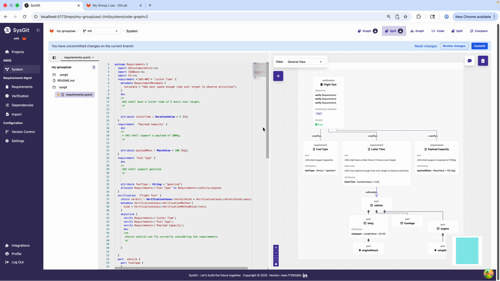
The final integrated view shows:
SysML v2 Code (left panel) includes:
- Requirements package with three requirements
- Verification definition (Flight Test)
- Part definitions with hierarchy
- Allocation statement:
allocate Requirements::'Fuel Type' to Requirements::vehicle.engine;
Visual Graph (right panel) displays:
- Requirements cards with verification relationships
- Part hierarchy with vehicle and sub-parts
- Allocation arrow connecting Fuel Type requirement to the engine part
- Wing attributes (wingspan: 20 ft)
This complete model demonstrates:
- Structural decomposition: Vehicle composed of fuselage, wing, and engine
- Requirement traceability: Requirements allocated to implementing parts
- Verification planning: Flight Test verification defined for requirements
- Engineering attributes: Parts have typed, quantified properties
Interfaces and Ports#
Interfaces define how parts connect and communicate. Properly modeled interfaces are critical for multi-vendor programs where subsystems are developed independently.
Port Definitions#
Ports represent connection points on parts:
part 'Flight Controller' {
    port powerIn : ElectricalPort {
        attribute voltage : ElectricPotentialValue = 28.0 [V];
        attribute maxCurrent : ElectricCurrentValue = 2.0 [A];
    }

    port canBus : CANPort {
        attribute baudRate : Real = 1000000 [bps];
    }

    port servoOutputs : ServoPort[8];  // Array of 8 servo connections
}
Ports have attributes that specify interface requirements. The Flight Controller requires 28V power input and provides 8 servo outputs.
Interface Definitions#
Interface definitions describe the contract between connecting parts:
interface def ElectricalPowerInterface {
    attribute voltage : ElectricPotentialValue;
    attribute maxCurrent : ElectricCurrentValue;
    attribute powerType : String;  // "DC" or "AC"
}

interface def CANBusInterface {
    attribute baudRate : Real [bps];
    attribute protocolVersion : String;
}
These interface definitions ensure that connecting parts have compatible specifications. If one part provides 28V and another requires 12V, the model reveals this mismatch.
Connections#
Connections link ports on different parts:
part drone {
    part battery : Battery;
    part flightController : FlightController;

    connect battery.powerOut to flightController.powerIn;
}
This connection documents that the battery's power output connects to the flight controller's power input. During integration, engineers can verify that the connection exists and meets interface requirements.
Working with the System Graph#
The System Graph View provides visual representation of your model structure. It's particularly useful for:
- Understanding architecture: See the complete system decomposition at a glance
- Navigating relationships: Follow connections between parts, requirements, and verifications
- Presenting to stakeholders: Project the graph in reviews to show system structure
- Identifying patterns: Spot highly connected parts or isolated elements
Graph Layout#
The graph automatically arranges elements in a hierarchical layout:
- Top-level packages and systems appear at the top
- Nested parts appear below their parents
- Relationships appear as labeled edges
You can:
- Zoom in/out to control detail level
- Pan to navigate large models
- Click elements to see details in the side panel
- Filter to show only specific element types or packages
Creating Parts in Graph View#
You can create new parts directly in the graph:
- Click the "+" button at the bottom of a package or part
- Select "Part Definition" or "Part Usage"
- Enter the name
- Fill in attributes in the details panel
The new part appears in the graph immediately and in the code view simultaneously.
Code View for System Models#
The Code View shows the underlying SysML v2 textual notation for your system model. Advanced users often prefer working directly in code for efficiency.
Example System Model Code#
package System {
    part 'Complex Drone System' {
        part 'Propulsion System' {
            attribute maxThrust : ForceValue = 500.0 [N];
            attribute fuelCapacity : VolumeValue = 50.0 [L];

            part 'Engine' {
                attribute displacement : VolumeValue = 1.5 [L];
                attribute maxRPM : Real = 8000.0 [rpm];
            }

            part 'Fuel Tank' {
                attribute capacity : VolumeValue = 50.0 [L];
                attribute dryMass : MassValue = 8.0 [kg];
            }
        }

        part 'Power System' {
            attribute nominalVoltage : ElectricPotentialValue = 28.0 [V];

            part mainBattery : Battery {
                attribute capacity = 5000.0 [mAh];
                attribute voltage = 14.8 [V];
                attribute mass = 1.2 [kg];
            }
        }
    }
}
The code view enables:
- Efficient bulk creation: Type multiple parts quickly without clicking through dialogs
- Copy/paste: Duplicate similar structures and modify
- Search/replace: Make consistent changes across the model
- Version control review: See exactly what changed in diffs
Code Editing Best Practices#
Use indentation to show hierarchy: Nested parts should be indented consistently
Group related parts: Keep subsystems together in the code for readability
Add comments for complex structures:
part 'Avionics Bay' {
    // Primary flight control computers
    part fcc1 : FlightController;
    part fcc2 : FlightController;  // Redundant

    // Navigation sensors
    part gps : GPSReceiver;
    part imu : IMU;
}
Use consistent naming: Follow your organization's naming conventions
Commit frequently: Small commits make code review easier
Package Organization#
For large systems, organize your model into multiple packages:
package System {
    package Propulsion {
        part 'Propulsion System' { /* ... */ }
    }

    package Avionics {
        part 'Flight Control System' { /* ... */ }
        part 'Communication System' { /* ... */ }
    }

    package Structures {
        part 'Airframe' { /* ... */ }
    }
}
Benefits of package organization:
- Team focus: Each team works primarily in their package
- Access control: Repositories can be structured by package
- Reusability: Packages can be shared across projects
- Scalability: Large models remain navigable
Mass and Power Budgets#
System models enable roll-up calculations for critical parameters like mass and power consumption.
Defining a Budget Model#
part drone {
    attribute totalMass : MassValue;

    part 'Propulsion System' {
        attribute allocatedMass : MassValue = 15.0 [kg];
        attribute actualMass : MassValue = 14.2 [kg];
    }

    part 'Power System' {
        attribute allocatedMass : MassValue = 5.0 [kg];
        attribute actualMass : MassValue = 5.3 [kg];
    }

    // totalMass = sum of all subsystem actualMass values
}
While SysGit doesn't automatically calculate roll-ups, documenting the structure enables external tools (Python scripts, spreadsheets, CI/CD pipelines) to extract data and perform calculations.
Budget Requirements#
Link budget requirements to the model:
requirement <'SYS-010'> 'Maximum Takeoff Weight' {
    doc /* System shall have maximum takeoff weight ≤ 55 kg */
    attribute maxMass : MassValue = 55.0 [kg];
}

// Allocate to top-level system
allocate Requirements::'Maximum Takeoff Weight' to 'Drone';

// Derive to subsystem budgets
requirement <'PROP-010'> 'Propulsion Mass Budget' {
    doc /* Propulsion system shall have mass ≤ 15 kg */
    attribute allocatedMass : MassValue = 15.0 [kg];
}

allocate Requirements::'Propulsion Mass Budget' to 'Drone'.'Propulsion System';
This creates formal traceability from top-level constraints to subsystem budgets.
Multi-Vendor System Models#
In multi-organization programs, the system model defines boundaries between vendors.
Interface Control Documents#
The system model captures ICDs:
interface def PropulsionInterface {
    // Mechanical interface
    attribute mountingHolePattern : String = "4x M6 bolts, 100mm square";
    attribute maxVibration : Real = 5.0 [g];

    // Electrical interface
    attribute powerInput : ElectricPotentialValue = 28.0 [V];
    attribute maxCurrent : ElectricCurrentValue = 10.0 [A];

    // Control interface
    attribute controlProtocol : String = "CAN 2.0B";
    attribute baudRate : Real = 1000000 [bps];
}

part 'Propulsion System' {
    port airframeMount : MechanicalInterface;
    port powerInput : ElectricalInterface;
    port controlBus : CANInterface;
}
Subcontractors receive the interface definitions and must ensure their designs comply.
Subsystem Allocation#
Allocate requirements to subsystems, then let each vendor implement:
Prime contractor model:
part 'UAV System' {
    part 'Propulsion System' {
        // Interface definitions only
        // Vendor A implements internal details
    }

    part 'Avionics System' {
        // Interface definitions only
        // Vendor B implements internal details
    }
}
Each vendor maintains their own detailed model in their own repository, linked through interfaces.
Committing Your Changes#
After defining parts and allocations:
- Click Review changes in the notification banner
- Review the generated SysML v2 code
- Add a commit message (e.g., "Added parts: vehicle, wing, fuselage, engine with allocations")
- Click Commit to save to the Git repository
All parts, attributes, and allocation relationships are stored as plaintext SysML v2 in your Git repository, enabling:
- Version control for system architecture
- Collaborative modeling through branching and merging
- Traceability and audit trails
- Integration with CI/CD pipelines
Best Practices#
Start with High-Level Structure#
Begin with major subsystems before decomposing into details. This provides context and helps identify interfaces early.
Align with Organization#
Structure your model to match team organization. If you have separate propulsion and avionics teams, have separate propulsion and avionics subsystems.
Define Interfaces Early#
Interface problems are expensive to fix late in development. Define ports and interfaces as you structure the system, not as an afterthought.
Use Part Definitions for Standard Parts#
If a component appears multiple times, define it once and instantiate as needed. This ensures consistency and makes updates easier.
Attribute Consistency#
Use the same attribute names and types across similar parts. This enables automated analysis and roll-ups.
Document Rationale#
Add comments explaining why the structure is organized this way, especially for non-obvious decomposition decisions.
Review Regularly#
System architecture evolves. Review the model regularly and refactor as needed. Use Git branching to explore structural changes without affecting the baseline.
Keep Requirements Synchronized#
As system structure changes, review requirement allocations. New subsystems may need requirements flowed down; removed subsystems need reallocation.
Common Patterns#
Functional vs Physical Decomposition#
Some systems use functional decomposition (what the system does):
part 'UAV System' {
    part 'Navigation Function';
    part 'Communication Function';
    part 'Propulsion Function';
}
Others use physical decomposition (physical groupings):
part 'UAV System' {
    part 'Avionics Bay';
    part 'Engine Assembly';
    part 'Airframe Structure';
}
Choose the decomposition that best supports your development process. Many programs use hybrid approaches.
Redundancy Modeling#
Model redundant systems explicitly:
part 'Flight Control' {
    part fcc1 : FlightControlComputer {
        attribute channel = "Primary";
    }

    part fcc2 : FlightControlComputer {
        attribute channel = "Backup";
    }
}
This makes redundancy visible in the architecture and enables modeling failure modes.
Modular Architecture#
Design for modularity:
part 'Payload Bay' {
    port payloadInterface : PayloadInterface;

    // Different payload modules can connect here
    part currentPayload : SensorPackageA;
}
This flexibility supports variant systems and mission-specific configurations.
Next Steps#
After defining parts:
- Add ports and interfaces for component interactions
- Define connection relationships between parts
- Add more detailed attributes and constraints
- Create alternative architectures using Git branches
- Establish verification methods for part-level requirements
See Also#
- Requirements Management: Creating requirements that allocate to system parts
- Traceability: Managing allocation relationships in matrices and graphs
- Verification Management: Verifying that parts meet allocated requirements
- SysML v2 Language Reference: Complete syntax for parts, attributes, and interfaces
- Advanced SysML v2 techniques for complex models